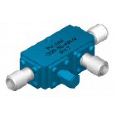
Digital
Digital Phase Shifters
Switched Bit Digital Controlled, 0.05-4.00 GHz
These digital phase shifters utilize switched lines to obtain temperature stable phase shift. The phase is specified at the center frequency ± 1.5% and is proportional to frequency over the entire band.| Frequency Range (GHz) | Insertion Loss (dB) max. | VSWR (dB) max. | Phase Range | Number of Bits | Least Significant Bit (LSB) | P/N |
|---|---|---|---|---|---|---|
| 0.05-0.06 | 3.5 | 1.50:1 | 360° | 8 | 1.4° | DST-15-480/1S |
| 0.25-0.50 | 6.0 | 1.80:1 | 360° | 8 | 1.4° | DST-10-480/1S |
| 0.50-1.00 | 4.5 | 1.80:1 | 360° | 8 | 1.4° | DST-11-480/1S |
| 1.25-1.35 | 3.5 | 1.80:1 | 360° | 8 | 1.4° | DST-14-480/1S |
| 1.00-2.00 | 4.5 | 1.80:1 | 360° | 8 | 1.4° | DST-12-480/1S |
| 2.00-4.00 | 6.0 | 1.80:1 | 360° | 8 | 1.4° | DST-13-480/1S |
Custom frequency bands and optimized specifications available.
Notes: Other frequency bands and resolution ranges available. Phase is ± 1.5% at center frequency.
General Specifications  Operating Power: 20 dBm/100 mw max.. Operating Power: 20 dBm/100 mw max..  Power Handling: +30 dBm/1 watt max. Power Handling: +30 dBm/1 watt max.  Switching Time: 500 nsec max. Switching Time: 500 nsec max.  Control Logic: TTL Control Logic: TTL Power supply: ± 5 Vdc @ ± 300 mA, Typical. Power supply: ± 5 Vdc @ ± 300 mA, Typical. Temperature: -25° C to +80° C Temperature: -25° C to +80° C RF Connectors: SMA Female RF Connectors: SMA Female Bi-directional. Either J1 or J2 can be used as input. Bi-directional. Either J1 or J2 can be used as input. J3 - DC Connector (DC Power & Logic): J3 - DC Connector (DC Power & Logic):
ITT Cannon, 15 Pin
 Pin 01 = Phase: 1.4 (LSB) Pin 02 = Phase: 2.8 Pin 03 = Phase: 5.6 Pin 04 = Phase: 11.25  Pin 05 = Phase: 22.5 Pin 06 = Phase: 45 Pin 07 = Phase: 90 Pin 08 = Phase: 180 Pin 09 = N/C Pin 10 = N/C Pin 11 = N/C Pin 12 = N/C Pin 13 = +5 Vdc Pin 14 = -5 Vdc Pin 15 = GND |
 Outline 480/1S |
| Outline | Conn. | A | B | C | D | E | G |
|---|---|---|---|---|---|---|---|
| 480/1S | SMA | 5.00 | 3.00 | .75 | .250 | 1.50 | .150 |

Новости
Новые продукты от VivaTech
06.02.2018
VivaTech предлагает новые решения для применений в миллиметровом / THz диапазонах.
Новые продукты от A-Info
23.12.2016
AINFO предлагает к поставке новый волноводный ответвлитель и логопериодические антенны с простой и двойной поляризацией


