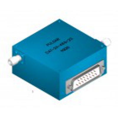
Digital Controlled, 4-18 GHz
Our family of digitally programmable attenuators cover the frequency range of 4-16 GHz. Attenuation ranges of 32 dB and 64 dB are standard, with 8 bits of resolution. LSB of 32 dB models is 0.125 dB, and for 64 dB models LSB is 0.250 dB. Each model includes an internal integrated linearized driver, an internal clock, and a D/A converter. Options of 12 bits resolution are available.
| Frequency Range (GHz) | Insertion Loss (dB) max. | VSWR (dB) max. | Attenuation Range (dB) | Number of Bits | Least Significant Bit (LSB) | P/N |
|---|---|---|---|---|---|---|
| 4.00-8.00 | 5.5 | 2.00:1 | 32 | 8 | 0.125 | DAT-14-482/1S |
| 4.00-8.00 | 6.0 | 2.00:1 | 64 | 8 | 0.250 | DAT-19-482/1S |
| 8.0-12.40 | 5.5 | 2.00:1 | 32 | 8 | 0.125 | DAT-20-482/1S |
| 8.0-12.40 | 6.0 | 2.00:1 | 64 | 8 | 0.250 | DAT-21-482/1S |
| 6.0-16.00 | 5.5 | 2.00:1 | 32 | 8 | 0.125 | DAT-22-482/1S |
| 6.0-16.00 | 6.0 | 2.00:1 | 64 | 8 | 0.250 | DAT-23-482/1S |
| 6.0-18.00 | 6.0 | 2.00:1 | 32 | 8 | 0.125 | DAT-24-482/1S |
| 6.0-18.00 | 6.5 | 2.00:1 | 64 | 8 | 0.250 | DAT-25-482/1S |
Custom frequency bands and optimized specifications available.
General Specifications  Resolution of 8 bit is standard; up to 12 bits available. Resolution of 8 bit is standard; up to 12 bits available.  Operating Power <= 0 dBm Operating Power <= 0 dBm Power Handling = +27 dBm max. Power Handling = +27 dBm max. Switching Time: 600 nsec typical. Switching Time: 600 nsec typical. Control Logic: TTL Control Logic: TTL Power supply: +12 to +15 Volts @ +100 mA, Typical Power supply: +12 to +15 Volts @ +100 mA, Typical-12 to -15 Volts @ -50 mA, Typical  Operating Temperature: -25°C to + 80°C C Operating Temperature: -25°C to + 80°C C RF Connectors: SMA Female RF Connectors: SMA Female These attenuators are bi-directional. Either J1 or J2 can be used as input. These attenuators are bi-directional. Either J1 or J2 can be used as input. J3 - DC Connector (DC Power & Logic): J3 - DC Connector (DC Power & Logic):ITT Cannon, 15 Pin
 Pin 01 = Bit 1 (LSB) Pin 02 = Bit 2  Pin 03 = Bit 3 Pin 04 = Bit 4 Pin 05 = Bit 5 Pin 06 = Bit 6 Pin 07 = Bit 7 Pin 08 = Bit 8 Pin 09 = N/C Pin 10 = N/C Pin 11 = N/C Pin 12 = N/C Pin 13 = +8 to +15 VDC Pin 14 = -8 to -15 VDC Pin 15 = Ground |
| Bandwidth (2:1) | Bandwidth (4:1) | |||
|---|---|---|---|---|
| Flatness (dB) | Attenuation (dB) | Flatness (dB) | Attenuation (dB) | |
| ± 0.5 | 0-10 | ± 0.6 | 0-10 | |
| ± 0.8 | 0-20 | ± 1.2 | 0-20 | |
| ± 1.2 | 0-30 | ± 1.8 | 0-30 | |
| ± 1.5 | 0-40 | ± 2.2 | 0-40 | |
| ± 2.2 | 0-64 | ± 3.5 | 0-64 | |
 Outline 482/1S |
Новости
Новые продукты от VivaTech
06.02.2018
VivaTech предлагает новые решения для применений в миллиметровом / THz диапазонах.
Новые продукты от A-Info
23.12.2016
AINFO предлагает к поставке новый волноводный ответвлитель и логопериодические антенны с простой и двойной поляризацией


