Broadband Directional Couplers 560 Series
Broadband Directional Couplers 560 Series

| Description | Features |
|
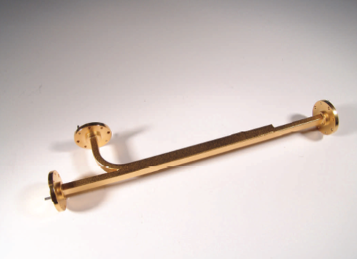
Mi-Waves’ 560 series broadband directional couplers are broadwall E-plane multi-hole energy-coupling devices. The 560 series couplers are designed in 8 waveguide sizes from 12.4 to 110 GHz. Nominal couplings of 3 dB, 6 dB, 10 dB, 20 dB, 30 dB, and 40 dB re offered to complement specific test set requirements.
|
• Broadband •Low VSWR • E-plane design • High Directivity • Rugged Construction • High Coupling Accuracy • Calibrated Coupling Values • Minimum Coupling Variation |
| Dimensional Specifications | ||||||
| Model No. | A | B | C | |||
| in | mm | in | mm | in | mm | |
| 560K/10, 20, 30, 40 | 11.50 | 292.0 | 2.00 | 50.8 | 1.50 | 38.1 |
| 560K/3, 6 dB | 12.75 | 323.9 | 2.00 | 50.8 | 1.50 | 38.1 |
| 560A/10, 20, 30, 40 | 9.62 | 244.0 | 1.75 | 44.5 | 1.38 | 35.1 |
| 560A/3, 6 dB | 12.0 | 304.8 | 1.75 | 44.5 | 1.38 | 35.1 |
| 560B/10, 20, 30, 40 | 8.40 | 213.0 | 1.64 | 41.7 | 1.30 | 33.0 |
| 560B/3, 6 dB | 10.25 | 259.1 | 1.64 | 41.7 | 1.30 | 33.0 |
| 560U/10, 20, 30, 40 | 7.38 | 187.4 | 1.38 | 35.1 | 1.12 | 28.5 |
| 560U/3, 6 dB | 9.12 | 231.6 | 1.38 | 35.1 | 1.12 | 28.5 |
| 560V/10, 20, 30, 40 | 6.25 | 159.0 | 1.13 | 28.6 | 0.88 | 22.4 |
| 560V/3, 6 dB | 7.25 | 184.1 | 1.13 | 28.7 | 0.88 | 22.4 |
| 560E/10, 20, 30, 40 | 5.50 | 140.0 | 1.13 | 28.5 | 0.88 | 22.4 |
| 560E/3, 6 dB | 6.62 | 168.1 | 1.13 | 28.7 | 0.88 | 22.4 |
| 560W/10, 20, 30, 40 | 4.50 | 114.0 | 1.00 | 25.4 | 0.81 | 20.6 |
| 560W/3, 6 dB | 5.50 | 139.7 | 1.00 | 25.4 | 0.81 | 20.6 |
| |
||||||
| Technical Specifications | ||||||||
| Model Number | 560K | 560A | 560B | 560U | 560V | 560E | 560W | |
| Frequency Band (GHz) |
18.0- 26.5 |
26.5- 40.0 |
33.0- 50.0 |
40.0- 60.0 |
50.0- 75.0 |
60.0- 90.0 |
75.0- 110.0 |
|
| Coupling (dB) | ------3, 6, 10, 20, 30, 40------ | |||||||
| Coupling Variation (dB) |
± 0.6 | ± 0.6 | ± 0.6 | ± 0.8 | ± 1.0 | ± 1.0 | ± 1.0 | |
| Coupling Accuracy (dB) |
± 1.0 | ± 1.0 | ± 1.0 | ± 1.2 | ± 1.5 | ± 1.5 | ± 1.5 | |
| Directivity (dB) Typical | 40 | 40 | 40 | 40 | 40 | 40 | 40 | |
| Main Line VSWR | 1.05 | 1.05 | 1.05 | 1.10 | 1.10 | 1.10 | 1.10 | |
| Auxiliary Line VSWR | 1.12 | 1.12 | 1.12 | 1.15 | 1.15 | 1.15 | 1.17 | |
Новости
Новые продукты от VivaTech
06.02.2018
VivaTech предлагает новые решения для применений в миллиметровом / THz диапазонах.
Новые продукты от A-Info
23.12.2016
AINFO предлагает к поставке новый волноводный ответвлитель и логопериодические антенны с простой и двойной поляризацией


